


What Is An Indexable Drill:A Complete Guide
 Jul 17, 2026|
 View:74
Every machining shop faces the same challenge: how to drill holes faster, at lower cost, and with less waste — especially when dealing with larger diameters and tougher materials. The indexable drill has become one of the most widely adopted solutions in modern metal cutting, yet many buyers and engineers still have questions about how it actually works and whether it is right for their operation. This complete guide answers all of those questions in plain language.
An indexable drill uses replaceable carbide inserts mounted in a reusable steel holder body — only the insert is discarded when worn.
It is most cost-effective for hole diameters above 12 mm, where the savings over solid carbide tools are greatest.
Compared with HSS twist drills, indexable drilling systems can reduce cycle times by up to 85% in roughing applications.
Standard systems handle depths of 3×D to 4×D; advanced modular designs reach 25×D.
Selecting the right insert grade and coating for the workpiece material is critical to maximising tool life.
Proper coolant supply — ideally through the spindle — is essential for chip evacuation and insert protection.
1. What Is an Indexable Drill?
An indexable drill is a type of cutting tool used on CNC machining centres, milling machines, and lathes to create round holes in metal and other materials. Unlike a conventional twist drill or solid carbide drill — where the entire tool is discarded or reground when the cutting edge wears — an indexable drill separates the tool into two parts: a holder body that remains in service indefinitely, and replaceable cutting inserts that are swapped out when they become dull or damaged.
The word "indexable" refers to the ability to rotate (index) an insert to present a fresh cutting edge, or to remove the insert entirely and fit a brand-new one — all without removing the drill body from the machine. This modular concept is what makes the indexable drilling system so appealing in high-volume production environments.
Indexable drills are sometimes called insert drills, U-drills, or indexable insert drills. Regardless of the name, the core principle is the same: the expensive, precision-ground holder body is reused, while only the low-cost insert is consumed.
2. Key Components of an Indexable Drilling System
Understanding the individual parts of an indexable drilling system makes it easier to select, use, and maintain the tool correctly.
2.1 The Drill Body (Holder)
The drill body is typically made from alloy steel and is precision-machined to hold inserts in exactly the right position. It features helical or straight flutes that channel chips and coolant away from the cutting zone. The body also contains internal coolant passages that direct fluid to the cutting edges — a critical feature for effective chip evacuation, particularly in deep-hole drilling.
2.2 The Cutting Inserts
Most indexable drills use two inserts: a center (inner) insert and a peripheral (outer) insert. These two inserts perform different jobs. The center insert cuts at effectively zero surface speed near the drill's axis, so it must be made from a tougher grade of carbide. The peripheral insert operates at full cutting speed and defines the final hole diameter. Together, they cover the full cross-section of the hole in a single pass.
Inserts are available in various carbide grades and coatings — uncoated, TiN, TiCN, TiAlN, and other advanced coatings — to match different workpiece materials and cutting conditions. Chipbreaker geometries are also varied: standard chipbreakers suit cast iron and harder steels, while dimple-style chipbreakers help control the long, stringy chips produced by soft low-carbon steels.
2.3 The Insert Clamping System
Inserts are held in place by precision-machined pockets within the drill body and secured with clamping screws (typically Torx-type). A secure clamping system is essential — any movement of the insert during cutting results in poor hole quality and potential tool damage. High-quality indexable drills feature pockets with tight tolerances and hardened locating surfaces to ensure the insert seats perfectly every time.
2.4 The Shank and Mounting Interface
The drill shank connects the tool to the machine spindle or toolholder. Common shank styles include cylindrical, Weldon flat, HSK, and steep-taper interfaces, depending on the machine type and power requirements. For deep-hole applications, extension bars or modular adapters are used to reach the required depth without compromising rigidity.
| Component | Material / Type | Function | Service Life |
|---|---|---|---|
| Drill Body (Holder) | Alloy Steel | Supports inserts, provides flutes and coolant channels | Indefinite (reusable) |
| Center Insert | Carbide (tougher grade) | Cuts inner portion near drill axis | Replaced when worn |
| Peripheral Insert | Carbide (wear-resistant grade) | Cuts outer diameter; defines final hole size | Replaced when worn |
| Insert Screws | Hardened alloy | Clamp inserts securely in pocket | Replace every ~10 insert changes |
| Shank | Alloy Steel | Connects tool to machine spindle | Indefinite (reusable) |
3. How Does an Indexable Drill Work?
The operating principle of an indexable drill bit is straightforward. When the drill rotates and advances into the workpiece, both inserts cut simultaneously. The inner insert removes material from the centre of the hole, and the outer insert defines the final diameter. Because neither insert needs to cut all the way from the axis to the full radius on its own, the cutting forces are distributed more evenly across the tool, reducing thrust and minimising deflection.
Chips generated at the cutting zone are transported upward through the flutes, assisted by coolant flowing from the internal passages. Good chip management is crucial: if chips are not evacuated cleanly, they re-enter the cut, damaging both the insert and the hole surface.
When an insert wears out, the operator simply loosens the clamping screw, removes the worn insert, inserts a fresh one, and torques the screw to the specified value. The entire process typically takes under two minutes — far faster than resetting or resharpening a solid drill. For a detailed breakdown of insert drill geometry, Cutting Tool Engineering's technical reference on indexable drilling provides excellent background reading.
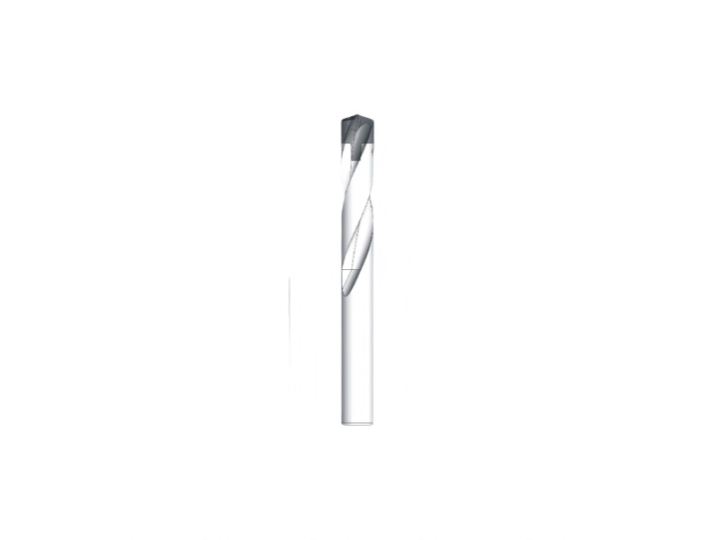
4. Indexable Drill vs. Other Drill Types: Key Differences
Choosing between an indexable drill and another tool type depends on hole diameter, depth, material, volume, and budget. The table below summarises the main trade-offs.
| Feature | Indexable Drill | Solid Carbide Drill | HSS Twist Drill |
|---|---|---|---|
| Initial Cost | Moderate (holder + inserts) | High | Low |
| Running Cost per Hole | Low (replace only insert) | High (replace whole tool) | Low–Moderate (regrinding possible) |
| Best Diameter Range | > 12 mm (0.5") | 0.1 mm – ~25 mm | Any diameter |
| Cutting Speed | High (carbide inserts) | Very High | Low–Moderate |
| Typical Max Depth | 3×D – 25×D (system-dependent) | Up to 30×D | Up to 10×D (with pecking) |
| Insert Change Time | < 2 minutes | N/A (whole tool) | N/A (whole tool or regrind) |
| Hole Tolerance | Good (±0.05 mm typical) | Excellent | Moderate |
| Material Waste | Minimal (holder reused) | High | Moderate |
For a broader comparison of spade drills and indexable drills across insert types and coatings, MSC Industrial's drilling guide provides useful reference data on tool selection by material group.
5. Advantages of Using an Indexable Drilling System
5.1 Lower Cost per Hole
Because the drill body is reused and only the small carbide inserts are replaced, the tooling cost per hole drops significantly compared to solid carbide drills — especially at diameters above 12 mm, where solid tools are expensive. In heavy-equipment and structural-steel applications, where hundreds of large-diameter holes may be drilled daily, the cost advantage is substantial.
5.2 Faster Cycle Times
Carbide inserts allow far higher cutting speeds than HSS tools. Case studies in roughing operations have shown cycle time reductions of up to 85% when switching from HSS twist drills to indexable carbide drilling systems. Higher penetration rates mean more holes drilled per shift with the same machine.
5.3 Minimal Downtime for Tool Changes
Insert replacement takes under two minutes without removing the drill body from the spindle. This is a major productivity advantage in high-volume environments where machine downtime is costly.
5.4 Versatility Across Materials
By selecting the appropriate insert grade and coating, the same drill body can be used across a wide range of workpiece materials — from aluminium alloys and cast iron to stainless steel and titanium. This flexibility reduces the number of different tools that must be stocked.
5.5 Environmental Sustainability
The modular approach dramatically reduces material waste. Only the small cutting insert — a fraction of the total tool mass — is discarded. The steel drill body, which represents most of the material and embodied energy, continues in service. For manufacturers with sustainability targets, this is an increasingly important factor.
5.6 Consistency and Repeatability
Precision-ground insert pockets ensure that every fresh insert seats in exactly the same position, maintaining consistent hole diameter and position from insert to insert. This repeatability is essential in automated CNC environments where human adjustment between holes is not practical.
6. Common Applications of Indexable Drills
The indexable drilling system has found a home across virtually every sector that requires large-diameter hole making in metal.
| Industry | Typical Application | Why Indexable Drills Excel |
|---|---|---|
| Heavy Equipment Manufacturing | Rough and semi-finish holes in frames, housings, brackets | High material-removal rate; low cost at large diameters |
| Structural Steel Fabrication | Bolt holes and connection holes in beams and plates | Fast penetration; no resharpening needed |
| Automotive Manufacturing | Engine blocks, cylinder heads, transmission cases | Consistent hole quality in high-volume runs |
| Aerospace | Structural frame holes in aluminium and titanium | Specialised insert grades for difficult alloys |
| Oil & Gas / Energy | Flanges, valve bodies, manifold drilling | Handles tough alloys; deep-hole capability |
| General Machining | Any production hole > 12 mm in steel or cast iron | Best overall productivity-to-cost ratio |
7. Choosing the Right Indexable Drill Bit: What to Consider
7.1 Diameter and Depth
Indexable drills deliver the greatest advantage for diameters above 12 mm. For depth-to-diameter (L/D) ratios up to 4×D, standard short-series bodies are appropriate. For deeper holes — 5×D, 7×D, or beyond — longer bodies or modular extension systems are required. Note that feed rates typically need to be reduced at greater depths (for example, reducing feed by approximately 15–30% when moving from 3×D to 5–7×D) to maintain stability.
7.2 Workpiece Material
Insert grade selection is closely tied to the workpiece material. The general guidance is:
Carbon and alloy steels: coated carbide (TiN or TiAlN); standard chipbreaker geometry.
Stainless steel and hardened steel (> HB 250): tough carbide grade; standard chipbreaker; reduce cutting speed versus steel.
Cast iron: uncoated or TiN-coated carbide; standard chipbreaker; dry or mist coolant acceptable.
Aluminium and soft non-ferrous alloys: polished or PCD inserts; high cutting speeds (500–2,500 SFM); flood coolant recommended.
Titanium and high-temperature alloys: TiAlN-coated inserts; lower cutting speeds; high coolant pressure essential.
7.3 Coolant Delivery
Through-spindle internal coolant is strongly preferred for indexable drilling, particularly for holes deeper than 2×D. It delivers coolant directly to the cutting edges, flushes chips out of the hole, and keeps inserts cool. External coolant alone is often insufficient at higher depths and speeds. Coolant pressure and flow volume should match the drill diameter — larger drills require higher flow rates.
7.4 Machine Rigidity
Indexable drills generate significant radial and axial forces. The machine spindle must be in good condition with minimal run-out; a run-out exceeding ±0.005 inch (0.13 mm) TIR typically results in oversized holes and accelerated insert wear. Workpiece fixturing must also be rigid — any flex in the setup is amplified at the cutting edge.
7.5 Mounting Type
Most modern indexable drills use a mechanical screw-clamping system that requires no adhesives or special tools. Verify that the drill body's shank size and interface type are compatible with the machine's spindle or toolholder before ordering.
8. Technical Specifications to Know
| Parameter | Typical Range / Notes |
|---|---|
| Recommended Diameter Range | 12 mm – 80 mm (0.5" – ~3.15"); optimal cost advantage above 12 mm |
| L/D Ratio (standard) | 3×D – 4×D for most short-series drills |
| L/D Ratio (advanced modular) | Up to 25×D with appropriate holder systems |
| Cutting Speed — Carbon Steel | 200–400 SFM (60–120 m/min) with coated carbide inserts |
| Cutting Speed — Aluminium | 500–2,500 SFM (150–760 m/min) |
| Cutting Speed — Stainless Steel | 100–250 SFM (30–76 m/min) |
| Feed Rate (general range) | 0.003"–0.012" per revolution (0.08–0.30 mm/rev); varies by diameter and material |
| Run-out Tolerance (max recommended) | ±0.005" (0.13 mm) TIR |
| Hole Tolerance (typical) | IT9–IT11 (±0.03–0.15 mm depending on diameter) |
| Coolant Delivery | Internal (through-spindle) preferred; 100–150 psi for most applications |
| Insert Replacement Time | Under 2 minutes per insert |
For further technical guidance on speeds and feeds by material group, MSC Industrial's indexable drilling reference and Cutting Tool Engineering's in-depth analysis both offer comprehensive data tables.
9. Best Practices for Using Indexable Drills
9.1 Surface Preparation
Indexable drills perform poorly on convex, curved, or inclined entry surfaces. If the workpiece surface is not flat, mill a small flat spot (spot face) before drilling. This two-step approach adds only seconds to the cycle but prevents the outer insert from deflecting on entry — a common cause of chipped edges and off-centre holes.
9.2 Avoid Peck Drilling
Unlike HSS drills, indexable drills should not be peck-drilled unless absolutely unavoidable. Each re-entry of the insert into the cut is a high-stress event that accelerates edge chipping. Instead, optimise coolant pressure and flow to maintain continuous chip evacuation during a single-pass cut.
9.3 Reduce Feed at Entry and Exit
Reducing the feed rate to approximately 50% for the first and last 0.1 inch (2.5 mm) of the cut protects the peripheral insert from snapping as the drill breaks through rough or uneven surfaces. Once stable in the cut, the full programmed feed rate can be resumed.
9.4 Monitor Insert Screws
Insert clamping screws experience significant thermal cycling and mechanical stress. Replacing them every ten insert changes is a low-cost precaution that prevents screw failure mid-cut — an event that can result in insert loss and potential workpiece damage.
9.5 Clean Insert Pockets at Every Change
Chip debris or coolant deposits in the insert pocket prevent the insert from seating flat, leading to run-out and inconsistent hole dimensions. A quick wipe with a clean cloth and a visual check for burrs or nicks in the pocket takes only seconds but makes a significant difference in tool performance.
9.6 Read the Chip
Chip shape is the most immediate feedback tool available. Short, tightly curled chips indicate correct cutting conditions. Long, stringy chips suggest the feed rate is too low relative to cutting speed — increase feed or reduce speed. Powdery or dusty chips in hard materials indicate excessive heat and the need for more coolant or a reduction in speed.
10. Alpha Technology's Series C Indexable Drilling System
For buyers evaluating a reliable indexable drilling system, Alpha Technology's Series C is designed specifically to address the most common challenges in large-diameter hole making. The system combines a proprietary holder geometry with precision-ground, replaceable inserts to deliver consistent hole quality across a wide range of applications.
| Parameter | Series C Specification |
|---|---|
| L/D Range | 3×D – 25×D |
| Target Diameter | D > 12 mm |
| Cooling System | Internal and External |
| Mounting Type | Mechanical (no adhesives required) |
| Insert Feature | Fully Replaceable |
| Cost Advantage vs. Conventional Systems | Up to 50% lower tooling cost |
| Product Series | INDEXABLE |
The unique holder geometry of Series C provides exceptional insert clamping security and precise positioning, eliminating the risk of insert movement during aggressive machining operations. The deep L/D capability (up to 25×D) extends the system well beyond what conventional indexable drills offer, making it suitable for deep structural holes and long-reach applications.
The modular design also aligns with sustainability objectives: because the holder body is never discarded, only the small insert contributes to tooling waste — a meaningful advantage for manufacturers managing environmental impact alongside operational costs.
Ready to Upgrade Your Drilling Operation?
Alpha Technology specialises in high-performance indexable drilling systems for manufacturers worldwide. Get expert advice and a competitive quotation tailored to your application.
Send an Enquiry Now11. Summary
An indexable drill consists of a reusable holder and replaceable carbide inserts — the insert is the only consumable part.
The system is best suited for hole diameters above 12 mm, offering the strongest cost and productivity advantages over solid carbide and HSS alternatives at larger sizes.
Proper setup — correct run-out, flat entry surface, adequate coolant, and appropriate insert grade — is as important as the tool itself.
Advanced indexable drilling systems such as Alpha Technology's Series C extend deep-hole capability to 25×D while maintaining up to 50% lower tooling cost versus conventional approaches.
Sustainability is a growing reason to adopt indexable drills: holder reuse dramatically reduces material waste compared to disposable solid tools.


